3D Helicopter
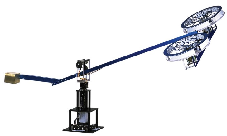
The 3D Helicopter consists of a base upon which an arm is mounted. The arm carries the helicopter body on one end and a counterweight on the other. The arm can pitch about an ìelevationî axis as well as swivel about a vertical (travel) axis. Encoders mounted on these axes allow for measuring the elevation and travel of the arm. The helicopter body is mounted at the end of the arm. The helicopter body is free to swivel about a ìpitchî axis. The pitch angle is measured via a third encoder. Two motors with propellers mounted on the helicopter body can generate a force proportional to the voltage applied to the motors. The force generated by the propellers can cause the helicopter body to lift off the ground. The purpose of the counterweight is to reduce the power requirements on the motors. The counterweight is adjusted such that applying about 1.5 volts to each motor results in hover. All electrical signals to and from the arm are transmitted via a slip-ring with 8 contacts thus eliminating the possibility of tangled wires and reducing the amount of friction and loading about the moving axes. The purpose of the experiment is to design a controller that allows you to command the helicopter body to a desired elevation and a desired travel rate or position.
Control techniques studied:
- System Modeling & Simulation
- Frequency Analysis
- Disturbance Rejection
- Tracking Control & Regulation
- Control of Coupled Systems
- Multivariable Real-time Control
- Full State Feedback ñ Pole Placement Technique
- Observer Design & Implementation
- Root Locus Design
- Non Linear Friction
- Hardware in the Loop
- Discrete Time Sampling - System Identification