XUtils
XUtils>System>NiOx
Current Function Version: 1.1 (June/25/'09)
Brief Description
This function provides several useful measures on your XEDS systems in AEMs, using Ray Egerton's NiOx thin film test specimen. Namely,
- Energy resolution of the XEDS detector
- Inverse hole-count (sometimes also called film count)
- Peak-to-Background ratio in Fiori definition
- Conventional total Peak-to-Background ratio
- Mo K/L ratio
- Detector solid angle (detector collection angle)
- Detector efficiency (figure-of-merit for detection)
Usage
Open an X-ray spectrum measured from the NiOx thin film in Gatan DigitalMicrograph. You can also import an X-ray spectrum using the EMSA file import plug-in. Make sure that the opened/imported X-ray spectrum is the front image, and then select XUtils>System>NiOx from the menu bar. Then, following dialog appears.
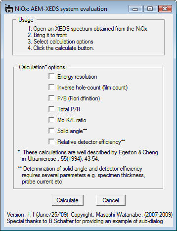
You can click any check box which you want to determine and click the Calculate button. If you select either solid-angle determination or detector efficiencydetermination, following sub-dialog appears.
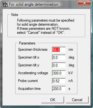
These parameters are required for determinations of the solid angle and detector efficiency. Most of these parameters should be extracted from the tag of the spectrum if information is properly saved. However, you must input the film-thickness since the thickness value is not usually saved in the EMSA format and thickness of the NiOx film varies depending on the batch. You can find the thickness value from the original instruction sheet enclosed together with the NiOx thin specimen. Once you input these parameters, click the OK button.
Results
Here are examples of the results.
- Energy resolution
- Inverse hole-count
- Peak-to-Background ratio in Fiori definition
- Conventional total Peak-to-Background ratio
- Mo K/L ratio
- Detector solid angle (detector collection angle)
- Detector efficiency (figure-of-merit for detection)
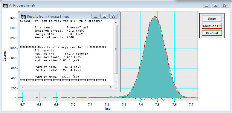
The energy resolution of an XEDS detector is defined as the full-width-at-half-maximum (FWHM) value at the Mn Ka peak position (5.9 keV). This value can be derived from the FWHM value of the Ni Ka peak as:
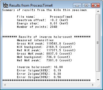
The inverse hole-count is defined as an intensity ratio between the Ni Ka and the Mo Ka peaks measured from the NiO film part. This measure is for evaluation of stray electrons and X-rays in an AEM column. For modern AEMs, this value is around 3-7.
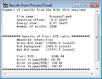
This peak-to-background ratio is defined as the Ni Ka intensity above the background divided by the background intensity at a single channel. For modern AEMs, this value can be as high as 3000.
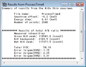
This peak-to-background ratio is defined as the Ni Ka intensity above the background divided by the full background intensity.
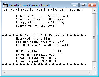
The Mo K/L ratio can also be used to evaluate stray irradiation of your instrument. The stray X-rays would produce a high Mo K/L ratio since high-energy bremsstrahlung X-rays preferentially generate the high energy Mo Ka line. In contrast, the stray electrons may excite rather the Mo La than the Mo Ka.
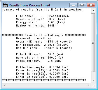
The detector solid angle can be calculated as:
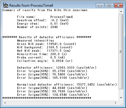
The detector efficiency is defined as the count rate (cps) divided by the probe current (nA) and the collection angle (sr). Therefore, this measure can be calculated as:
The normalized detector efficiency is determined from the detector efficiency divided by the weight fraction of Ni. So, this value corresponds to the efficiency of the Ni Ka line from pure Ni instead of NiO. As long as normalized or regular value is compared consistently, you can use either value.
Acknowledgements
Many thanks to Bernhard Schaffer (FELMI/ZFE, Graz University of Technology) for providing me a great example of sub-dialog creation (i.e., Bernhard kindly agreed to be "pushed" by me).
