Pottstown Machine Company
Photographs (circa 1900-1932)
Held by Special Collections, Linderman Library
Lehigh University, Bethlehem, Pennsylvania 18015
Call No.: SC Photo 0003
5 Boxes; 366 Photographs
Abstract:
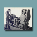
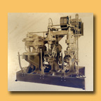
Pottstown Machine Company Photographs (circa 1900-1932) contains 366 photographs, one advertisement, and an inventory. Each of these items relate to the Pottstown Machine Company, Pottstown, Pennsylvania. The subjects of the photographs are the various machines the company manufactured. Some include the interior of the company’s buildings and/or personnel. The advertisement includes a photograph of a man using one of the machines and a short description of the machine. The list contains descriptions of some of the photographs (see Boxes 4-5.)
The collection was acquired by Lehigh University’s Special Collections in November, 2006.
Contact Information:
Special Collections
Linderman Library
Lehigh University
Bethlehem, Pennsylvania 18015, USA
Phone: 610-758 4506
Fax: 610-758 6091
URL: http://www.lehigh.edu/library/speccoll/specialcoll.html
Processed by:
Erin K. Martell
Repository:
Lehigh University, Linderman Library, Special Collections
Creator:
Pottstown Machine Company (Pottstown, Pennsylvania)
(Several photographs were stamped or written on the back with different names. These may have been the names of photographers or other companies. They are listed below.)
The Arrow System
W.H. Barber
Davis Studios C. D. Hilles, Prop., Pottstown, PA
Artist Charge
W.N. Jennings Photography, 10 South 18th St. Phila., PA
General Electric (G.E.)
Southern Fittings & Foundry Co.
The Strong, Carlisle and Hammond Co.
Title:
Pottstown Machine Company Photographs (circa 1900-1932)
Restrictions to Access:
This collection is open for research.
Preferred Citation:
[Identification of item], Pottstown Machine Company Photographs (circa 1900-1932), SC Photo 0003, Special Collections, Linderman Library, Lehigh University, Bethlehem PA
Copyright Notice:
Please inquire about copyright information.
Historical Sketch:
The Pottstown Machine Company was founded in 1895 by John R. Saylor. It was located at Rohland Street and the Reading Railroad on a five-acre piece of land. From the start, the company “specialized in general machinery-service work, and in the production of gray-iron castings.” (Chancellor 98) It also serviced “narrow-gauge locomotives for the Eastern Steel Company; as well as general service work for the steel and wrought-iron industries of Pottstown” throughout its earlier years. (Chancellor 98)
During the early 1900s, the company started to manufacture fitting-tapping machines and other “specialized tools for threading, tapping, and other operations on pipe fittings, valves, electrical fittings, and similar products.” (Chancellor 98) This became the primary work of the company for many years, which led to the development and use of the term “Pottstown tappers” around the world. These specialized tools were utilized by important local firms, along with others in the United States, Canada, Mexico, some South American countries, England, Palestine, South Africa, Australia, and many countries in Europe.
Beyond these specialized tools, the company provided service and foundry work for many principal industries both in Pottstown and surrounding areas. Throughout both World Wars, the company produced “heavy-duty latches for turning shells, along with other equipment for military use.” (Chancellor 99) As of 1953, the company had “approximately 100 employees, and included in its facilities are a gray-iron foundry, pattern shop, forge and heat-treating shop, and machine shops.” (Chancellor 99) Saylor was president and owner of the company from 1895 until his death in October, 1926. His widow, Mrs. Elizabeth E. Saylor succeeded him as president. The company was formally incorporated in July, 1926.
American Society of Mechanical Engineers. Transactions of the American Society of
Mechanical Engineers. 48 (1927): 1448.
Chancellor, Paul, Marjorie Potts Wendell and Paul Wescott. A History of Pottstown
Pennsylvania. Pennsylvania: The Historical Society of Pottstown, 1953; Reprinted
1974.
Biographical Sketch:
John R. Saylor was the founder, owner and president of the Pottstown Machine Company. Saylor was born on February 4, 1862 in Parkerford, PA. He obtained trade training as a machinist from the Ellis Keystone Agricultural Works in Pottstown, PA. He then went on to work for fifteen years at the Baldwin Locomotive Works in Philadelphia. Saylor was responsible for constructing the Baldwin exhibit for the World’s Fair, held in Chicago in 1893. In 1895, he started his own business called the Pottstown Machine Company. He was elected into the American Society of Mechanical Engineers in August, 1917. The company was formally incorporated in July, 1926. Saylor died on October 21, 1926 in his Pottstown home. Mrs. Elizabeth E. Saylor succeeded him as president of the company.
American Society of Mechanical Engineers. Transactions of the American Society of
Mechanical Engineers. 48 (1927): 1448.
Chancellor, Paul, Marjorie Potts Wendell and Paul Wescott. A History of Pottstown
Pennsylvania. Pennsylvania: The Historical Society of Pottstown, 1953; Reprinted
1974.
Scope and Content Note:
This collection contains 366 photographs, a four-page inventory, and one advertisement. The photographs are black and white and vary in size. Almost all of the photographs are of machines manufactured by the company. Several include the interior of the company’s buildings and/or personnel. Many of the photographs have written and/or stamped information on the front and/or back. This information includes company names (possibly photographers or purchasers) and/or information about the actual machines. Several of the photographs include a detailed caption, date and emblem from the General Electric Publicity Department. Part of the collection is an album that may have been used as a catalog. This album included four leaves of a typed list describing items in the photographs and a 5.75” x 6.75” advertisement piece showing a photograph of a man working on a machine and a written description of the machine. There are also two oversize photographs pasted on cardboard backings.
Organization of the Content:
The Pottstown Machine Company collection has been organized based on the manner in which it was received. There were five groups of photographs, which appeared to be arranged by size, and one album of photographs, which appear to have been for a catalog of the company’s products. All items in the collection have been placed in protective sleeves and divided into five different boxes and two envelopes. The album was taken apart and put into sleeves in the exact same order, in the interest of preservation. The five items that accompanied the album are stored in the beginning of Box 4. The two oversize photographs are stored in separate envelopes.
Online Catalog Terms:
Pottstown Machine Company
Strong, Carlisle & Hammond Company (Cleveland, Ohio)
Saylor, John R.
Jennings, William N.
General Electric
Photography, Industrial
Industrial Equipment – Photographs
Machine Shops – Photographs
Machine Shops – Pictorial Works
Automatic Machinery
Machine – tools
Metal-cutting -- Equipment and supplies -- Photographs
Taps and dies -- Photographs
Spindles (Machine-tools) -- Photographs
Spindles (Machine-tools) -- Equipment and supplies -- Photographs
Detailed Description of Collection:
Box 1:
This box contains seventy-nine 3.75” x 4.5”, sixty 6.5” x 4.5”, four 5.5” x 7”, and twelve 7.5” x 9.5” photographs. Several of the photographs have stamped names and/or written descriptions of the machine(s). Eight of the 7.5” x 9.5” photographs, in particular, have detailed captions, dates, and a stamp from the General Electric Publicity Department. Some of the photographs also include the interior of the building and/or personnel. Most of the descriptions provided below are copied directly from the photographs. When information was copied directly from a photograph, the original wording and capitalizations were maintained.
01.01
01.02 4 Spindle-Union Nut Ream. & Tapp. Machine
01.03
01.04 4 Spindle-Union Nut Ream. & Tapp. Machine
01.05
01.06 Southern Fittings & Foundry Co.
01.07 Southern Fittings & Foundry Co.
01.08 1 ¼ - 3 way Automatic Tapper - with Friction Clutch Rear View
01.09 1 ¼ - Three way – Auto Tapper – Friction Clutch; Pottstown Machine Co.; Magazine not Shown
01.10 1 ¼ - Three way – Auto Tapper – Friction Clutch; Pottstown Machine Co.; Magazine not Shown
01.11 Special 5 Station Reaming & Threading
01.12 Machine Rear View
01.13 The Arrow SystemàSuperior Quality
01.14 The Arrow SystemàSuperior Quality
01.15
01.16 The Arrow SystemàSuperior Quality; Ward 1
01.17
01.18 1” – Four Spindle – Union Nut – Ream. & Tapp. Mach.
01.19 5 Station – 4 Spindle – Reaming & Tapping Machine Rear View
01.20
01.21
01.22
01.23 Person also in photograph
01.24 2 Unit Group of 1” Conduit Body Tapping Machines Front View
01.25 2 Spindle Reaming and Threading Machine Left Rear View
01.26
01.27
01.28
01.29
01.30
01.31 W.H. Barber 9/12/38; People and interior of building also in photograph
01.32 W.H. Barber 9/12/38; People and interior of building also in photograph
01.33 W.H. Barber 9/12/38; Person and interior of building also in photograph
01.34 W.H. Barber 9/12/38; People and interior of building also in photograph
01.35
01.36 ¾” Fic. Auto. Tapping Machine Left Side View
01.37 W.H. Barber 9/12/38 Interior of building also in photograph
01.38 W.H. Barber 9/12/38; People and interior of building also in photograph
01.39
01.40
01.41
01.42 1” – Four Spindle – Union Nut – Ream. & Tapp. Mach.
01.43 The Arrow SystemàSuperior Quality
01.44
01.45
01.46
01.47 1” – 4 Spindle Automatic Bushing Machine with Friction Clutch Right Front View
01.48
01.49 2” – Five way Tapper
01.50
01.51
01.52
01.53 2 Unit Group of 1 ¼” Three way – Automatic – Magazine Fed Fitting Tapping Machines
01.54
01.55
01.56
01.57 1 ¼” Three way – Auto. Tapper – Friction Clutch; Magazine not shown
01.58
01.59
01.60 1” – 4 Spindle Automatic Bushing Machine with Friction Clutch Right Rear View
01.61
01.62 1 ¼” Three way – Auto. Tapper – Friction Clutch; Magazine not shown
01.63 4 Spindle – Union Nut – Ream. & Tapp. Machine
01.64
01.65
01.66
01.67 The Arrow SystemàSuperior Quality
01.68 5 Station – 4 Spindle – Reaming & Tapping Machine Front View
01.69
01.70
01.71 The Arrow SystemàSuperior Quality
01.72
01.73 Person also in photograph
01.74
01.75 1 ¼” Wide Range – Reversing Motor Tapper Rear View
01.76
01.77
01.78 1 ¼” Wide Range – Reversing Motor Tapper Rear View
01.79 Interior also in photograph
01.80
01.81 John R. Saylor, Prop.; 3 Unit 2” Tapping Machine
01.82 John R. Saylor, Prop.
01.83
01.84 John R. Saylor, Prop.
01.85 John R. Saylor, Prop.
01.86 for Tees 1 ¼”
01.87 John R. Saylor, Prop.
01.88
01.89
01.90
01.91 John R. Saylor, Prop.
01.92 John R. Saylor, Prop.
01.93
01.94 John R. Saylor, Prop.
01.95
01.96 John R. Saylor, Prop.
01.92 John R. Saylor, Prop.
01.93
01.94 John R. Saylor, Prop.
01.95
01.96 John R. Saylor, Prop.
01.97 John R. Saylor, Prop.
01.98 John R. Saylor, Prop.
01.99
01.100
01.101 John R. Saylor, Prop.
01.102 2 – Unit 6” Single Spindle Tapper
01.103
01.104
01.105
01.106
01.107
01.108 John R. Saylor, Prop.
01.109
01.110
01.111 John R. Saylor, Prop.
01.112
01.113
01.114
01.115 John R. Saylor, Prop.; Interior also in photograph
01.116 Interior also in photograph
01.117 John R. Saylor, Prop.; Interior also in photograph; Bushing Machine
01.118 Interior also in photograph
01.119 John R. Saylor, Prop.; 3 Unit 2” Tapping Machine
01.120 Interior also in photograph
01.121 Interior also in photograph
01.122 John R. Saylor, Prop.; Interior also in photograph
01.123 John R. Saylor, Prop.; Interior also in photograph; 5 Unit 1” Tapping Machine
01.124 Interior also in photograph
01.125 Interior also in photograph
01.126 Interior also in photograph
01.127 Interior also in photograph
01.128 Interior also in photograph
01.129 Interior also in photograph
01.130 John R. Saylor, Prop.; Interior also in photograph
01.131 John R. Saylor, Prop.; Interior also in photograph
01.132 Interior also in photograph
01.133 Interior also in photograph
01.134 Interior also in photograph
01.135 Interior also in photograph
01.136
01.137 John R. Saylor, Prop.
01.138
01.139
01.140
01.141
01.142
01.143
01.144 Davis Studios C.D. Hilles, Prop. Pottstown, PA
01.145 Bushing Machine
(Some of the following photographs include captions by G.E. Publicity Department)
01.146 G.E. Publicity Department; 479373; 8/13/31; 3 – Unit group of 1.25 – in. Automatic – Magazine – Fed, 3 – Way – Fitting Tapping Machines
(Photograph includes a caption)
01.147 G.E. Publicity Department; 479374; 8/18/31; 4 – Way Fitting Tapping Machine (Photograph includes a caption)
01.148 G.E. Publicity Department; 479374; 8/18/31; 4 - Way Fitting Tapping Machine (Photograph includes a caption)
01.149 G.E. Publicity Department; 479316; 8/13/31; 3 – Unit Group of 1.25 – in. Automatic – Magazine – Fed 3 – Way – Fitting Tapping Machines
(Photograph includes a caption)
01.150 G.E. Publicity Department; 479316; 8/13/31; 3 – Unit Group of 1.25 – in. Automatic – Magazine – Fed, 3 – Way – Fitting Tapping Machines
(Photograph includes a caption)
01.151
01.152
01.153 G.E. Publicity Department; 479372; 8/18/31; 4 – Way Fitting Tapping Machine (Photograph includes a caption)
01.154 G.E. Publicity Department; 479372; 8/18/31; 4 – Way Fitting Tapping Machine (Photograph includes a caption)
01.155 G.E. Publicity Department; 479373; 8/13/31; 3 – Unit Group of 1.25 – in. Automatic – Magazine – Fed, 3 – Way – Fitting Tapping Machines
(Photograph includes a caption)
Box 2:
This box contains thirty-five 7.25” x 9.25” photographs. Several of the photographs have stamped names and/or written descriptions of the machine. Some of the photographs also include the interior of the building and/or personnel. Most of the descriptions provided below are copied directly from the photographs. When information was copied directly from a photograph, the original wording and capitalizations were maintained.
02.156
02.157
02.158
02.159
02.160
02.161
02.162
02.163
02.164
02.165
02.166
02.167
02.168
02.169
02.170
02.171
02.172 Interior also in photograph
02.173
02.174 Received May 22, 1928 The Strong, Carlisle & Hammond Co.
02.175
02.176 2” Combination Union Machine Nut, Head and Tail Units; Artist Charge
02.177 Artist Charge; Four Unit 1 ¼” Three – Way Automatic Tapping Machine; 3 3/8” - 120 C silk paint out as attached sample
02.178
02.179
02.180
02.181
02.182
02.183
02.184
02.185 Person also in photograph
02.186
02.187
02.188
02.189 Automatic Tapping Machine 3 3/8
02.190
Box 3:
This box contains forty-three 7.25” x 9.25” photographs. A few of the photographs also include the interior of the building.
03.191
03.192
03.193
03.194
03.195
03.196
03.197
03.198
03.199
03.200 Interior also in photograph
03.201
03.202 Interior also in photograph
03.203
03.204
03.205
03.206
03.207
03.208
03.209
03.210
03.211
03.212
03.213
03.214
03.215
03.216
03.217
03.218
03.219
03.220
03.221
03.222
03.223
03.224 Interior also in photograph
03.225
03.226
03.227
03.228
03.229
03.230
03.231
03.232
03.233
Box 4:
This box contains sixty 7.25” x 9.5” photographs. These photographs came in an album that was disassembled in the interest of preservation. The photographs have been kept in their original order. The album was accompanied by four leaves of a typed list describing items in the photographs. The information from these lists has been copied directly to this aid, along with any additional information about and/or printed on the photographs. When information was copied directly from a photograph and/or list, the original wording and capitalizations were maintained. Also included in this box is a 5.75” x 6.75” advertisement piece showing a photograph of a man working on a machine and a written description of the machine.
Sheet 04.01-04 Three leaves of a typed list accompanied the album. They describe
the items in the album. The numbers and information from this list have been copied directly to this finding aid.
Sheet 04.05 Advertisement piece showing a man working on a machine and
including a description of the machine.
- June 1932; Interior also in photograph
- A-1. Front view – Single unit – ½” Magazine fed tapper – Positive clutch – mechanical chuck, belt drive
- A-2. Side view – Single unit – ½” Magazine fed tapper – Friction clutch – Air chuck, belt drive
- A-3. Side view of above
- A-4. Side view – Single unit – ½” Magazine fed tapper – Friction clutch – Air chuck, motor drive
- 1. Front view – Single unit ¾” Four way Tapper
- 2. Rear
- 3. Two unit ¾” Threeway Tapper
- 4. Three “ “ “ “
- 5. Four “ “ “ Full Automatic Tapper
- 5-A. Front view – four unit ¾” Magazine fed Tapper – Positive clutch
- 5-B. Front view – two unit ¾” Magazine fed tapper for unilets – Positive clutch
- 5-C. Back view – two unit ¾” magazine fed tapper friction clutch – Air chuck
- 5-D. Front view of above
- 6. Side view – Single unit – 1 ¼” Full Automatic Tapper
- 7. Front “ “ “ - 1 ¼” “ “ “
- 8. Rear “ “ “ - 1 ¼” “ “ “
- 8-A. Front view – 4 unit – 1 ¼” Magazine fed tapper – Positive clutch, Mechanical chuck
- 8-B. Rear view of above.
- 8-C. Front view – three unit 1 ¼” magazine fed tapper – Friction clutch, air chuck
- 8-D. Rear view of above
- 9. Front view single unit 1 ¼” full automatic tapper
- 10. Chuck on 2” threeway tapper; Interior also in photograph
- 11. Three unit 2” threeway tapper
- 12. Front view 2” Fiveway tapper
- 13. Rear view 2” fiveway tapper
- 14. Three unit 2” threeway full automatic tapper
- 15. Three unit 4” three and fourway tapper
- 16. Front view single unit 6” threeway tapper
- 17. Rear view single unit 6” threeway tapper
- 17-A. Front view – 6”- 3 way – Rev. A.C. Motor
- 17-B. Back “ “ “ “ “ “
- 18. Single unit 8” threeway tapper; Interior also in photograph
- 19. Two unit 1 ¼” single spindle tapper; Interior also in photograph
- 20. Front view three unit 1 ¼” single spindle tapper
- 21. Rear view three unit 1 ¼” single spindle tapper
- 22. Four unit 2” single spindle tapper
- 23. Single unit 4” single spindle tapper for Sanitary fittings
- 24. Single unit 6” single spindle tapper for Sanitary fittings
- 25. Single unit 6” single spindle tapper for Sanitary fittings – Double chuck
- 26. Single unit 6” single spindle Horizontal Tapper
- 27. Two unit 8” single spindle tapper for flanges
- 27-1. Side view 16” single spindle flange tapper; Davis Studios C.D.Hilles, Prop. Pottstown, PA; Copy made by Arrow 6/29/57 See envelope for film
- 27-A. Front view three unit 2” radiator nipple threading machine
- 27-B. Front view single unit 1” four spindle bushing machine – Automatic air index
- 27-C. Front view two unit 1” four spindle bushing machine – Automatic air index
- 27-D. Rear view of above
- 27-E. Front view two unit 1” four spindle bushing machine – Hand index
- 27-F. Front view - 1” – 4 Spdle. Bush. Mach. – Rev. A.C. motor
- 27-G. Back “ “ “ “ “ “ “ “
- 28. Front view two unit 2” bushing machine – Vertical
- 29. Rear view two unit 2” bushing machine – Vertical
- 30. Four unit 2” bushing machine – Vertical
- 30-A. Side view single unit 2” four spindle bushing machine – Automatic air index
- 30-B. Front view of above
- 30-C. Front view – 2” – 4 Spdle. Buch. Mach. – Rev. A.C. motor
- 30-D. Back “ “ “ “ “ “ “ “
- 31. Single unit 2” bushing machine – Vertical
- 32. Single unit 4” bushing machine – Vertical
- 33. Single unit 6” bushing machine – Vertical
Box 5:
This box contains seventy-one 7.25” x 9.5” photographs. They are a continuation of the photographs in Box 4, having come from the same album. Again, the information contained in the three leaves of a typed list accompanying the photographs has been copied directly to this finding aid. When information was copied directly from a photograph and/or list, the original wording and capitalizations were maintained. Any additional information about and/or printed on the photographs is also noted.
05.294 34. 2” Bushing underscoring machine
05.295 34-A. Front view 4 spindle plug machine with automatic extractor – Pulley drive
05.296 34-B. Same as above but motor drive
05.297 35. Four spindle plug machine – without extractor
05.298 35-A. Front view 6 spindle plug machine with automatic extractor – Pulley drive
05.299 35-B. Rear view of above
05.300 36. Rear view four spindle plug machine – without extractor
05.301 37. Single unit 1 ¼” Union Machine – Tail unit
05.302 38. Single unit 1 ¼” Union Nut machine
05.303 39. Two photographs numbered 39, but only one caption: Two inch Combined Union Machine
05.304 39. Two photographs numbered 39, but only one caption: Two inch Combined Union Machine
- 39-A. 2” Combination union machine with swinging turret
- 39-B. Same as above with air index
- 29-C. Same as above but with auxiliary heads
- 40. Three unit 2” union machine – head unit; Person also in photograph
- 41. Four unit 2” union machine – tail unit
- 42. Four unit 2” union nut machine
- 43. Two unit 2” Boiler ell machine – head end
- 44. Three spindle 1 ¼” special union machine – head unit; Person also in photograph
- 45. Three spindle 1 ¼” special union machine – tail unit
- 46. Special Union Machine 1 ¼”
- 47. Back view ¾” Valve Machine
- 48. Front view ¾” Valve Machine
- 49. Back view 2” Valve Machine – Friction index
- 50. Front view 2” Valve Machine – Friction Index
- 51. Front view 2” Valve machine – Air index
- 51-A. Front view special reaming and threading machine for condulets – 3 Work stations; Person and some interior also in photograph
- 51-B. Rear view of above
- 51-C. Front view – new 2” valve machine
- 51-D. L.H. Rear view of above
- 51-E. R.H. rear view of above
- 53. Back view 6” Valve Machine; Davis Studios C.D. Hilles, Prop. Pottstown, PA; Interior also in photograph
- 54. Front view 6” Valve Machine; Davis Studios C.D. Hilles, Prop. Pottstown, PA; Person and interior also in photograph
- 55. Vertical Swiper 25”
- 56. Three way facing machine 28”
- 57. Two spindle reaming machine for boiler sections
- 58. Typical Saylor Die
- 59. Saylor Die parts
- 60. Various sizes of Saylor dies
- 61. Special Return Bend Machine – 2” Rear view
- 62. Special Return Bend Machine – Front view
- 63. Front view 2” Return Bend Tapper – Old Style
- 63-A. Front view of new 2” Return Bend Machine
- 64. Reaming, tapping, facing machine for steam traps; Interior also in photograph
- 65. Reaming, tapping, facing machine for steam traps; Interior also in photograph
- 66. Gate valve boring and facing maching
- 67. Hexagon nut swiper – Rear view
- 68. Hexagon nut swiper – front view
- 69. 10” Flange facing and drilling maching
- 70. Threeway swiper 25” – front view; Person also in photograph
- 71. Threeway swiper – 25” – drive arrangement; Interior also in photograph
- 72. R.H. front view of Gang Tapper for boiler sections
- 72-A. L.H. Front view of above; Interior also in photograph
- 72-B. Front view of above; Interior also in photograph
- 73. Dean unit control for McCarthy Valve
- 74. 2 unit 2” solid fitting drilling and tapping machine
- 75. Front view – 6” Pipe threading machine – Rev. motor drive – AC
- 75-A. Back “ “ “ “ “ “ “ “ “
- 76. Front view- 2 Spindle reaming & threading maching
- 76-A. Back “ “ “ “ “ “ “
- 77. 2” – Gate Valve Seating Machine
- 78. Front View – 2 Unit – ¾” Reaming & Tapping Maching – H.B. Sherman
- 78A. Rear View “ “ “ “ “ “ “ “ “
- 79. 2” Pipe Coupling Machine – Scrapped
- 80. 3 Spindle Reaming Machine for boiler sections; Davis Studio C.D. Hilles, Prop. Pottstown, PA
- W.N. Jennings Photography 10 South 18th St. Phila., PA; G.E.
- W.N. Jennings Photography 10 South 18th St. Phila., PA; G.E.
- W.N. Jennings Photography 10 South 18th St. Phila., PA; G.E.; 6” Fourway – Detroit B. & M. Wks 0253 shipped June 30, 1931
- W.N. Jennings Photography 10 South 18th St. Phila., PA; G.E.
Box 6:
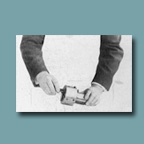
This box contains two oversize photographs. Both of the photographs are 7.5” x 9.5” and have been pasted on a cardboard backing. Photograph 365 is a print of a machine pasted on a 10” x 12” backing. Photograph 366 is a print of a machine part held by a man pasted on an 11” x 14” backing.
06.365 7.5” x 9.5” print of a machine pasted on a 10” x 12” cardboard backing
06.366 7.5” x 9.5” print of a machine part held by a man pasted on an 11” x 14” cardboard backing
Return to Special Collections Homepage